- Connect With Us!
- +92 345 3230843
- +971 54 454 5232
- solutions(at)eispak.com
Fire Pump Room

One of Best UL-Listed Fire Alarm System in Pakistan – SITERWELL
June 4, 2025
Clarke Fire Diesel Engine for Fire Pumps Applications in Pakistan
August 24, 2025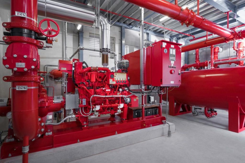
Component and Equipment
1- Gate valve
2- check valve
It prevents back flow, and allows only flow in on direction, and is installed in pump discharge line directly to prevent pumps from starting at a load or at the system pressure.
3- Suction header
It prevents vortex
4- Discharge header
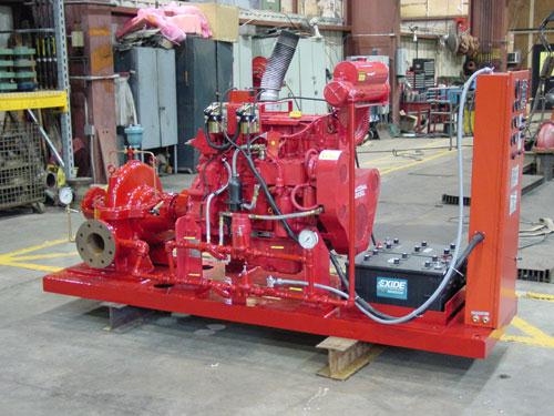
5- Diesel pump
It’s a 100% stand-by pump, operates in case of power failure with the failure of pressure make up process by the electric pump, or even with the present of power if failure of pressure makes up process.
6- Jockey pump
It’s the first pump to start in case of fire, It operates as a pressure maintenance pump so in case of a leakage in the system pressure it will makes the system pressure as recommended, and A jockey pump should be sized to make up the allowable leakage rate within 10 minutes or 1GPM (3.8 L/min), whichever is larger, and is used for this job instead-off starting the electric pump to protect it from starting until a serious problem occurs.
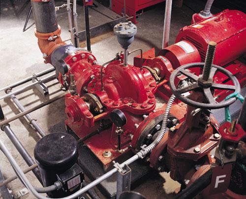
7- Electric pumps
It’s the second pump to start in case of fire; it’s the 100% duty pump.
8- Pressure relief valve
A valve being set at a pressure higher than the system pressure or shut off pressure of the diesel pump to protect the system from the very high pressure generated by the diesel pump in case of sudden acceleration.
9- Alarm check valve
It’s consisted of:
– Pressure switch (electric part) which gives a signal to fire alarm system in case of flow in pipes.
– Mechanical alarm which done automatically by water flow in pipes.
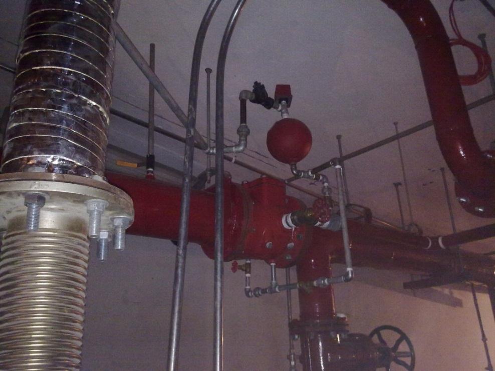
Fig-4 Alarm Check Valve
10- Water flow meter
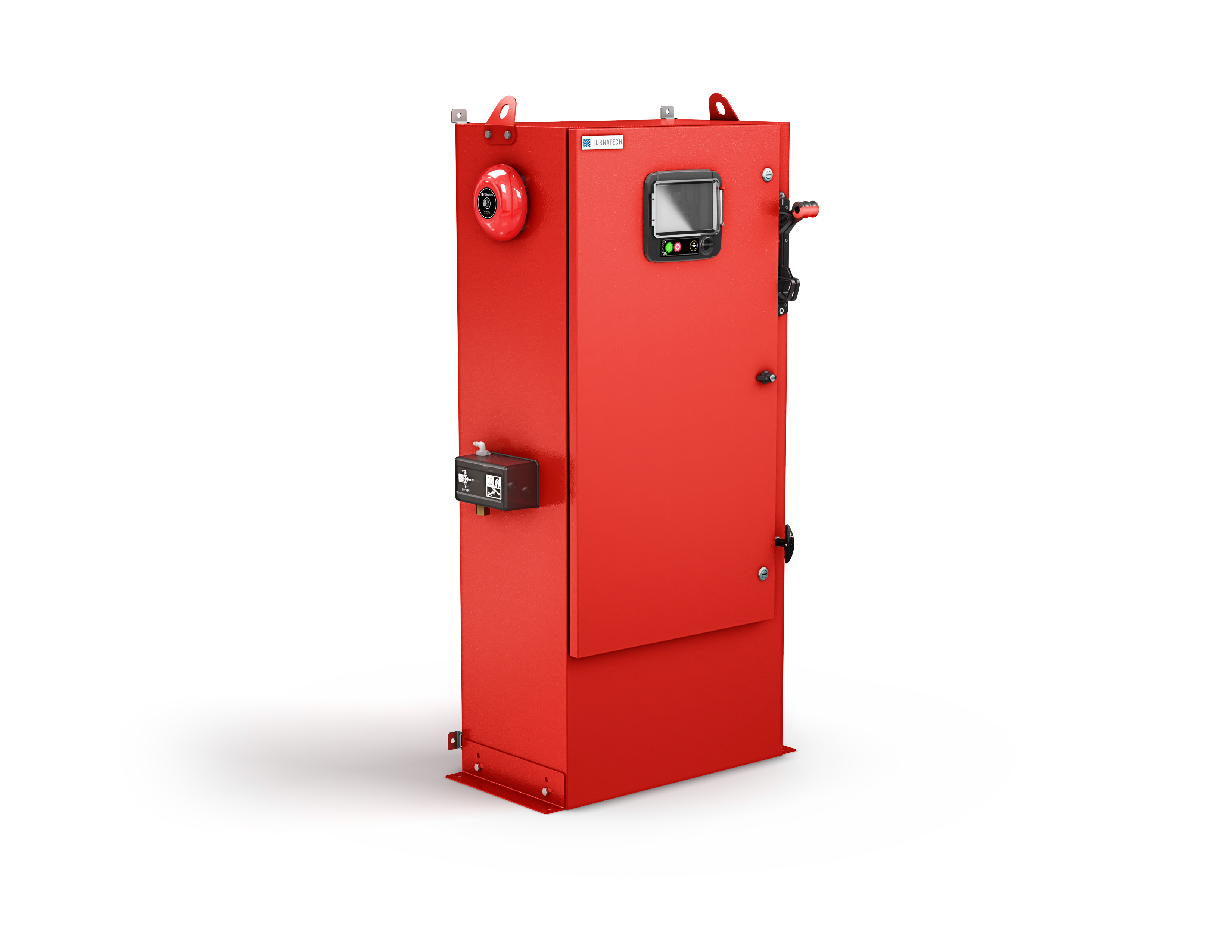
11- Diesel pump electric control panel and pressure sensing line
12- Jockey pump electric control panel and pressure sensing line
13- Electric pump electric control panel and pressure sensing line
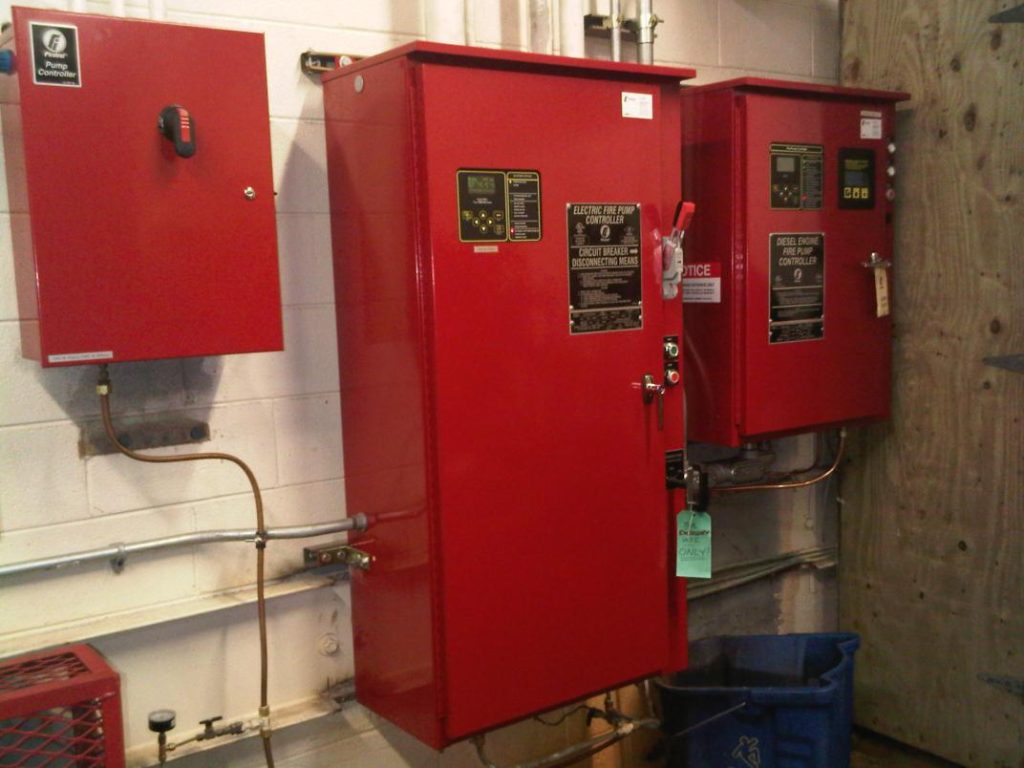
fig-5. fire pumps controllers
14- Vortex plate
It’s installed in the tank in suction lines to prevent vortex in the tank water.
15- Electric pump casing relief valve
It’s reliefs the pressure on the pump to protect it from damage in case of pump work and no exit for water in the system, and is being set at the shut of head or higher than system pressure.
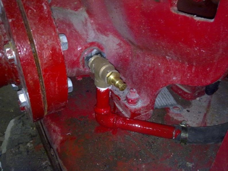
fig-6. casing relief valve
16- Stainless steel flexible joints
17- Automatic air vent
18- Tamper switch
It gives a signal when a gate valve closed.
19- Flow switch
It gives signal when a flow happened in a pipe.
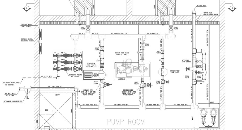
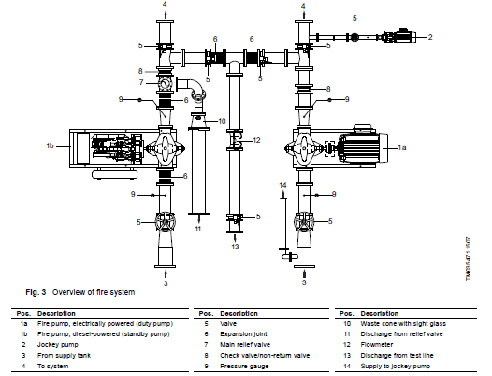
An arrangement for pump room:
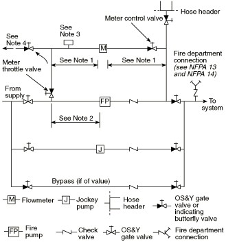
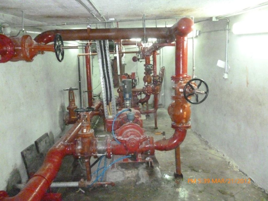
fig-8. firefighting pump room
Another arrangement for pump room:
Sequence of operation
All pipes of the wet system are maintained at a pressure higher than sys- tem demand pressure.
At first in case of fire a sprinkler open or a fire hose cabinet will be used This will makes the pressure of water to goes down, all pumps sensing
lines matched to pressure transducer in pump control panel, when the pressure reach 6 bar the pressure transducer in jockey pump controller gives signal to start the jockey, if the pressure maintained constant or goes high this means it just a leak, and if the pressure reached 5 bar the electric fire pump will start as same as jockey pump, and if the pressure reached 4 bar in any case the diesel pump will start by the same way.(all numbers is for example)
The fire pump operation is as follows
a- Motor-Driven Pump. To start a motor driven pump, the following steps should be taken in the order given below.
1- See that pump is completely primed.
2- Close isolating switch and then close circuit breaker.
3- Automatic controller will start pump if system demand is not satis- fied (e.g., pressure low, deluge tripped, etc.).
4- For manual operation, activate switch or pushbutton, or manual start handle.
Circuit breaker-tripping mechanism should be set so that it will not op- erate when current in circuit is excessively large.
b- Steam-Driven Pump. A steam turbine driving a fire pump should always be kept warmed up to permit instant operation at full rated speed.
The automatic starting of the turbine should not be dependent on any manual valve operation or period of low-speed operation. If the pop safety valve on the casing blows, steam should be shut off and the ex- haust piping examined for a possible closed valve or an obstructed por- tion of piping. Steam turbines are provided with governors to maintain speed at a predetermined point, with some adjustment for higher or low- er speeds. Desired speeds below this range can be obtained by throttling the main throttle valve.
The automatic starting of the turbine should not be dependent on any manual valve operation or period of low-speed operation. If the pop safety valve on the casing blows, steam should be shut off and the ex-haust piping examined for a possible closed valve or an obstructed por-tion of piping. Steam turbines are provided with governors to maintain speed at a predetermined point, with some adjustment for higher or low-er speeds. Desired speeds below this range can be obtained by throttling the main throttle valve.
c- Diesel Engine-Driven Pump. To start a diesel engine-driven pump, the operator should be familiar beforehand with the operation of this type of equipment. The instruction books issued by the engine and control manufacturer should be studied to this end.
The storage batteries should always be maintained in good order to en-sure prompt satisfactory operation of this equipment (i.e., check electro-lyte level and specific gravity, inspect cable conditions, corrosion, etc.).
(d) Fire Pump Settings. The fire pump system, when started by pres-sure drop, should be arranged as follows.
(1) The jockey pump stop point should equal the pump churn pressure plus the minimum static supply pressure.
(2) The jockey pump start point should be at least 10 psi (0.68-bar) less than the jockey pump stop point.
(3) The fire pump start point should be 5 psi (0.34 bar) less than the jockey pump start point. Use 10-psi (0.68-bar) increments for each additional pump.
(4) Where minimum run times are provided, the pump will continue to operate after attaining these pressures. The final pressures should not ex-ceed the pressure rating of the system.
(5) Where the operating differential of pressure switches does not permit these settings, the settings should be as close as equipment will permit. The settings should be established by pressures observed on test gauges.
(6) Example:
Pump: 1000-gpm, 100-psi pump with churn pressure of 115 psi.
Suction Supply: 50 psi from city — minimum static. 60 psi from city — maximum static.
Jockey pump stop = 115 + 50 = 165 psi.
Jockey pump start = 165 – 10 = 155 psi.
Fire pump stop = 115 + 50 = 165 psi.
Fire pump start = 155 – 5 = 150 psi.
Fire pump maximum churn = 115 + 60 = 175 psi.
(For SI units, 1 psi = 0.0689 bar.)
(7) Where minimum run timers are provided, the pumps will continue to operate at churn pressure beyond the stop setting. The final pressures should not exceed the pressure rating of the system components.
(e) Automatic Recorder. The performance of all fire pumps should be automatically indicated on a pressure recorder to provide a record of pump operation and assistance in fire loss investigation.
Shut off of the pumps
1- The Jockey pumps stops automatically when the pressure in pipes reached its rated pressure.
2- The Electric pump stops after reached the rated pressure by ten minutes
3- The Diesel pump stops after 30 minutes after reaching its rated pressure
Power Sources
There are two power sources:
- Normal
- Emergency
All pumps should be feed by the two ways of power in the building by the next ways:
The electric pump can be only feed by normal source if there is a diesel pumps but sometimes for safer it connected by the two sources.
The jockey should be feed the two sources.
The diesel pump needs to energize its battery in any time by this seAt first in the diesel pump control panel a charger this charger works in case of no electric charge in diesel battery so it energized the battery and out from the circuits, and when the battery charged the diesel will start automatically without any need of external power source, but by the time the battery could be damage or have a problem, so its preferable to make the diesel pump in the two power source.quence:
Note
Some codes allows to use two electric pumps one connected to normal source and one on the emergency source for cost reduction, but actually this way have some conditions must applied for safe, first is to make the generator very close to the pump room and all pumps cables must be fire rated (the second condition is for all fire system cables).
Types of fire pumps
Always used type of pumps for fire application is centrifugal vertical in-line or horizontal in-line.
Centrifugal pumps
Centrifugal pumps shall be of the overhung impeller between bearings design. The overhung impeller design shall be close coupled or separate-ly coupled single- or two-stage end suction-type [see Figures A-3-1.1(a) and (b)] or in-line-type [see Figures A-3-1.1(c), (d), and (e)] pumps. The impeller between bearings design shall be separately coupled single-stage or multistage axial (horizontal) split-case-type [see Figure A-3- 1.1(f)] or radial (vertical) split-case-type [see Figure A-3-1.1(g)] pumps.
{All figures are in the appendices}
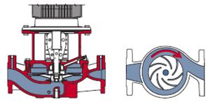
fig-10. flow in a centrifugal pump
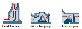
fig-11. types of flow in centrifugal pumps
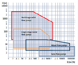
fig-12. ratings of centrifugal pumps
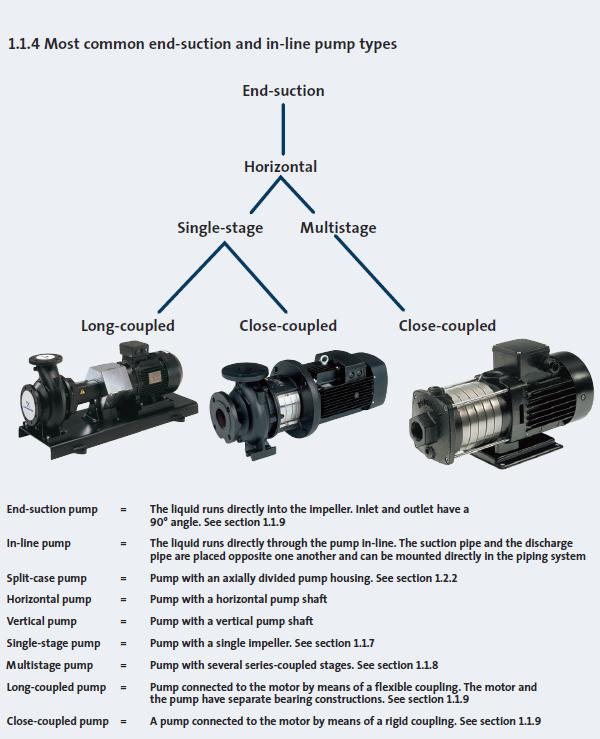
Figure-13 most end-suction and in-line pump types
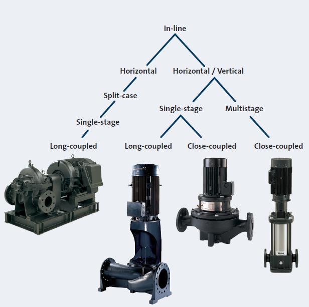
fig-14. classification of centrifugal pumps
Centrifugal pumps applications
Centrifugal pumps shall not be used where a static suction lift is re-quired.
Automatic Air Release
Pumps that are automatically controlled shall be provided with a listed float-operated air release valve having 1/2 in. (12.7 mm) minimum di-ameter discharged to atmosphere.
Exception: Overhung impeller-type pumps with top centerline discharge or vertically mounted to naturally vent the air.
Vertical Shaft Turbine-Type Pumps
Suitability
Where the water supply is located below the discharge flange centerline and the water supply pressure is insufficient for getting the water to the fire pump, a vertical shaft turbine-type pump shall be used.
Positive Displacement Pumps
Application
Positive displacement pumps are used for pumping water, foam concen-trates, or additives. The liquid viscosity will impact pump selection.
Selection of fire pumps
When selecting fire pumps you should be sure that the pump is specified for this application, UL listed FM approved and will pass the hydraulic test required for fire pumps.
When talking about different parameters of a pump:
Capacity, head of the pump and voltage frequency is all the needed data to select a pump.
The fire pump starts in a case of maintenance and emergency only so the loud sounds of it caused by higher RPM and higher power consumption will not be a problem and that for initial cost reduction, because the higher RPM the smaller the pump.
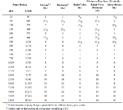
Sizing of pump accessories:
Table-pump accessories sizing
Installation cautions
All pumps should be installed in a fixed armed concrete base withstands lateral vibration by 1.5 times the weight of the pump.
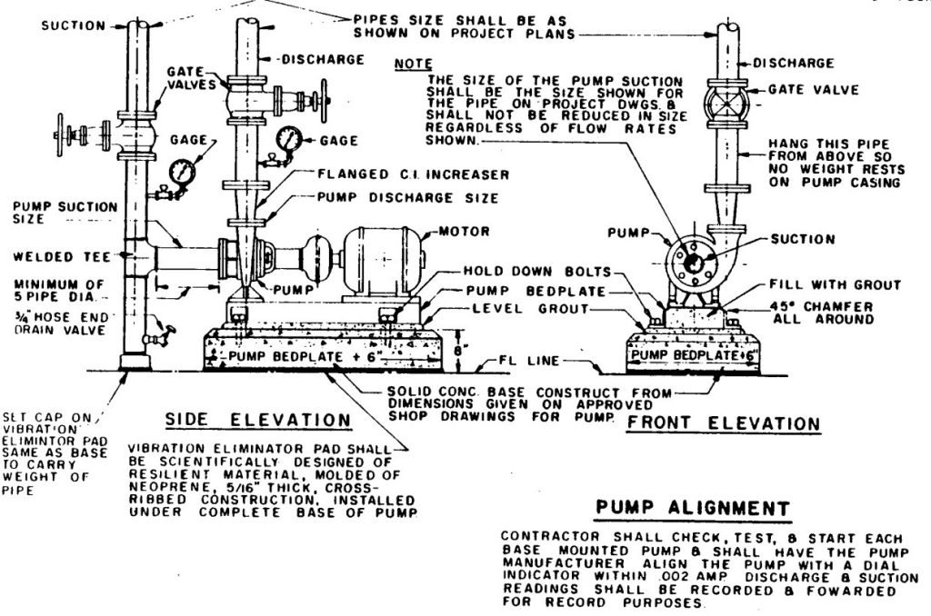
fig-15. fire pump installation
All elbows in pumps discharge should fixed with a support.
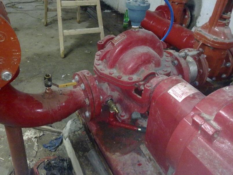
fig-16. elbows supports
Modulating valves after and before the metering device should be in- stalled by a special distance from the meter for accurate readings.
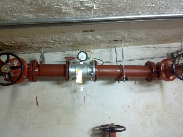
fig-17. installation of flow rate measuring device
Two check valves installed in each sensing line in the opposite direction of to the control panel should have at least 5 feet between each other and should be drilled by 3/32 inch drill.
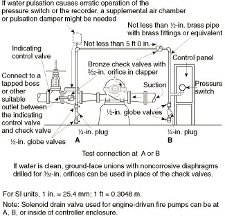
fig-18. Piping connection for each automatic pressure switch (for fire pump and jockey pumps).
Sensing lines materials should be series 300 stainless steel, brass or cop- per.
All sensing line size should be ½ inch.
Fire pumps installed by bolts in anchors which are welded in the armed base, the floor and base should be epoxy coated after all, and the pumps lying on a membrane rubber layer between it and the base.
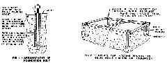
fig-19. installation of firefighting pumps base
Pressure relieving valve of the diesel pump should be connected to its discharge directly before the check valve.
The length of the exhaust pipe by the diesel pump must be coordinated with the supplier for allowable back pressure, and this pipe should be in- sulated with Aminat.
Fuel piping arrangement should be constructed be the supplier advise- ment.
Engines shall be started no less than once a week and run for no less than 30 minutes to attain normal running temperature. They shall run smoothly at rated speed.
The engine fuel supply (suction) connection shall be located on the tank so that 5 percent of the tank volume provides a sump volume not usable by the engine. The fuel supply shall be located on a side of the tank at the level of the 5 percent sump volume. The inlet to the fuel supply line shall be located so that its opening is no lower than the level of the en- gine fuel transfer pump. The engine manufacturer’s fuel pump static head pressure limits shall not be exceeded when the level of fuel in the tank is at a maximum.
{For fuel piping material and sizing please refer to appendices.}
Flame-resistant flexible hoses listed for this service shall be provided at the engine for connection to fuel system piping. There shall be no shutoff valve in the fuel return line to the tank.
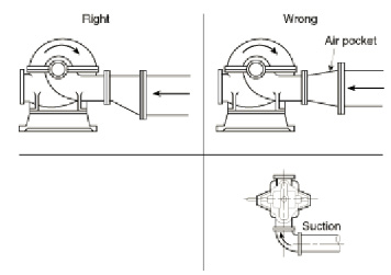
fig-20. Right and wrong pump suctions.
All the equipment and component should have to be UL listed and FM approved and a serial number.
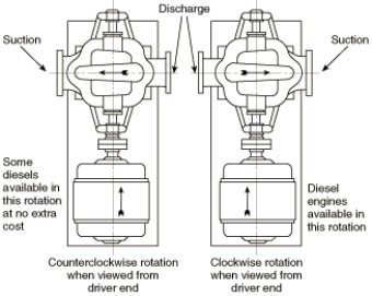
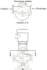
fig-22. Vertical pump shaft rotation
All pipes in the pump room should be hot dip galvanized if the source of water could cause rust of pipes or if the fire water tank and the domestic water tank is the same tank and pipes passes through the tank walls should be put into the wall when its being built not after that and if so it should been cured with special chemical insulation material.
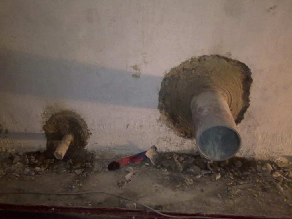
fig-23. Fig-17 pipes through tank walls
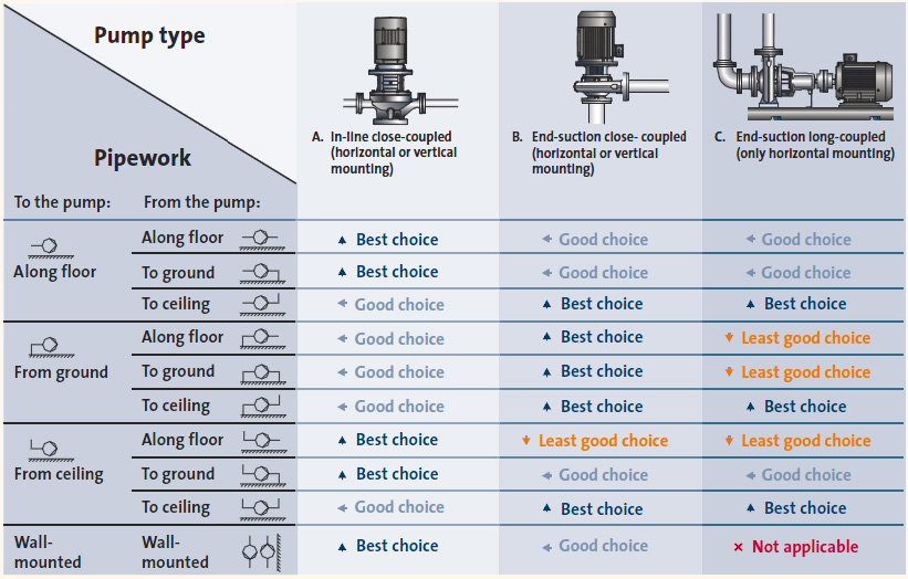
fig-24: Recommended type of a pump according to tank types
Hydraulic test
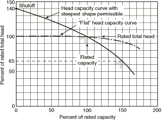
fig-25. Pump characteristics curves
Listed pumps can have different head capacity curve shapes for a given rating. Figure 18 illustrates the extremes of the curve shapes probable. Shutoff head will range from a minimum of 101 percent to a maximum of 140 percent of rated head. At 150 percent of rated capacity, head will range from a minimum of 65 percent to a maximum of just below rated head. Pump manufacturers can supply expected curves for their listed pumps.
Pumps Manufacturers
Excel Industrial Services offering the best brands options currently in the market
SUMMARY
🛠️ Core Components in a Fire Pump Room
- Gate Valve: Controls water flow; critical for maintenance isolation.
- Check Valve: Prevents backflow; installed directly on pump discharge lines.
- Diesel Pump: 100% standby unit for power outages. Starts at ≤4 bar pressure.
- Jockey Pump: First responder to leaks. Maintains system pressure (sized for 1 GPM/10 min makeup).
- Electric Pumps: Primary duty pumps; activate at ≤5 bar pressure.
- Pressure Relief Valve: Protects against diesel pump overpressure during sudden acceleration.
- Alarm Check Valve: Integrates pressure switches (fire alarm signals) and mechanical flow alarms.
- Vortex Plate: Prevents tank vortexes in suction lines.
- Tamper & Flow Switches: Monitor valve closures/water movement.
System Operations
- Sequence:
- Pressure drop to 6 bar → Jockey pump starts.
- Drop to 5 bar → Electric pump activates.
- Drop to 4 bar → Diesel pump engages.
- Shutdown:
- Jockey: Stops at rated pressure.
- Electric: Stops after 10 min at pressure.
- Diesel: Stops after 30 min.
Installation Best Practices
- Base: Fixed reinforced concrete (1.5x pump weight for vibration resistance).
- Piping:
- Galvanize pipes if water causes rust.
- Support all discharge elbows.
- Use ½” stainless steel/brass sensing lines.
- Diesel Systems:
- Exhaust pipes sized per backpressure limits (Aminat-insulated).
- Weekly 30-min test runs to maintain engine health.
Pump Selection & Sizing
- Types: Centrifugal (horizontal/vertical), Vertical Shaft Turbine (for low-supply pressure), Positive Displacement (foam/concentrates).
- Key Parameters: Capacity (GPM/LPM), Head (psi/bar), Voltage.
- Accessory Sizing:
| Pump Rating (GPM) | Suction (in.) | Discharge (in.) | Relief Valve (in.) |
|---|---|---|---|
| 100 | 2 | 2 | ½ |
| 500 | 5 | 5 | 3 |
| 2,000 | 10 | 10 | 6 |
Why Choose Excel Industrial Services?
Excel Industrial Services delivers end-to-end fire pump turnkey solutions—from design and UL/FM-compliant component selection to installation and maintenance. Our expertise ensures:
- NFPA 13/14-compliant pump room layouts.
- Seamless integration of jockey, electric, and diesel pumps.
- Lifetime system reliability with proactive maintenance programs.
➡️ Protect your assets with Excel—where safety meets precision engineering.
Pump Performance Curves
- Shutoff Head: 101–140% of rated head.
- 150% Capacity Head: 65% to just below rated head.
Partner with Excel Industrial Services—Your Fire Safety, Our Expertise.
#FirePump #FireProtection #PumpRoom #JockeyPump #DieselPump #ElectricPump #FireSafety #NFPA13 #NFPA14 #FireHydrant #SprinklerSystem #CentrifugalPump #WaterFlow #PressureRelief #CheckValve #VortexPlate #FireAlarm #TamperSwitch #FlowSwitch #FirePumpController #HydrantSystem #FirePrevention #IndustrialSafety #FireWaterTank #PumpInstallation #TurnkeySolutions #ExcelIndustrialServices #FirePumpMaintenance #ULListed #FMApproved #PumpAccessories #FirePumpTesting #EmergencyPower #DieselEngine #BatteryBackup #FirePumpCurves #FirePumpSizing #PumpRoomDesign #SuctionHeader #DischargeHeader #FirePumpValves #FirePumpSequence #FirePumpOperation #FirePumpTypes #VerticalPump #HorizontalPump #SplitCasePump #InLinePump #FirePumpRoom #FirePumpPanel #FirePumpControl #FirePumpPressure #FirePumpCables #FirePumpBase #FirePumpSupport #FirePumpPiping #GalvanizedPipes #FirePumpTesting #FirePumpManufacturers #FirePumpCertification #FirePumpStandards #FirePumpCompliance #FirePumpEfficiency #FirePumpRepair #FirePumpService #FirePumpSolutions #ExcelFirePump #FirePumpExperts #FirePumpPackage #FirePumpTurnkey #FirePumpDesign #FirePumpEngineering #FirePumpTech #FirePumpInnovation #FirePumpLeakage #FirePumpVibration #FirePumpNoise #FirePumpEfficiency #FirePumpCost #FirePumpRPM #FirePumpHead #FirePumpCapacity #FirePumpVoltage #FirePumpFrequency #FirePumpPriming #FirePumpGovernor #FirePumpGovernor #FirePumpRecorder #FirePumpVent #FirePumpAirRelease #FirePumpBypass #FirePumpMeter #FirePumpHose #FirePumpCabinet #FirePumpVent #FirePumpRelief #FirePumpBattery #FirePumpGenerator #FirePumpInsulation #FirePumpExhaust #FirePumpFuel #FirePumpRotation #FirePumpHydraulic #FirePumpTest #FirePumpCurve #FirePumpGPM #FirePumpLPM
