- Connect With Us!
- +92 345 3230843
- +971 54 454 5232
- solutions(at)eispak.com
TORNATECH DIESEL ENGINE FIRE PUMP CONTROLLERS – MODEL GPD – INSTALLATION AND MAINTENANCE MANUAL

Annual Fire Pump Performance Testing in Pakistan as per NFPA 25
August 26, 2025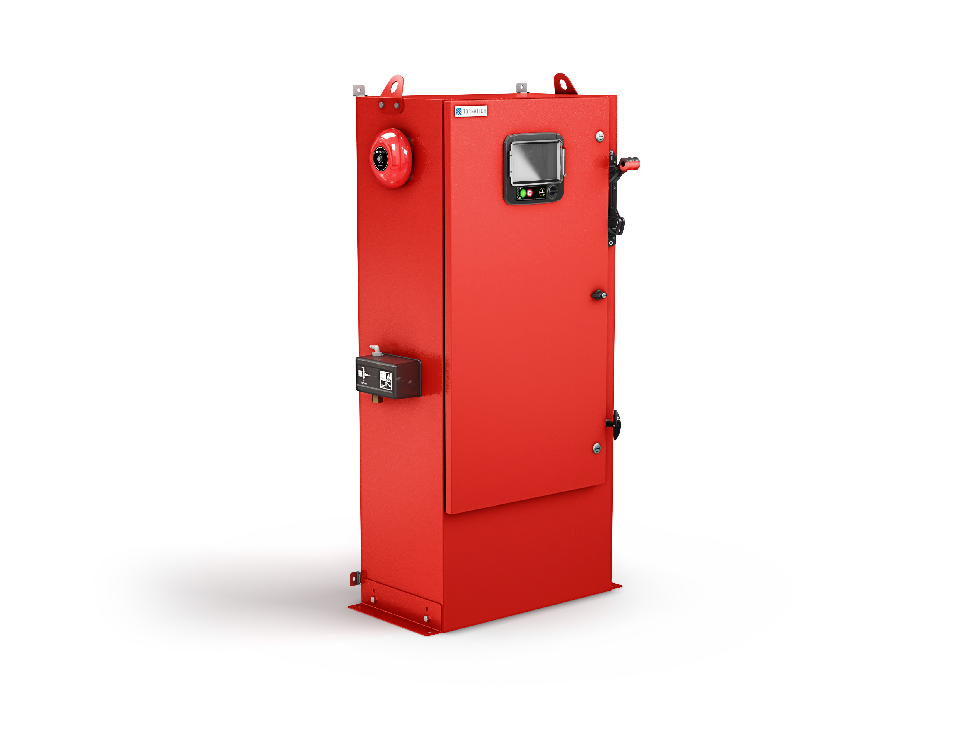
Tornatech Electric Fire Pump Controller – Model GPY – INSTALLATION, OPERATION AND MAINTENANCE MANUAL
August 28, 2025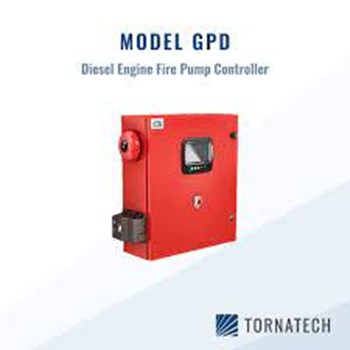
Table of Contents
- Introduction
- Types of Diesel Engine Fire Pump Controllers
- Methods of starting/stopping
- Installation
- FCC Regulations and Radio Standards Specification (RSS) Rules
- Location
- Mounting
- Wiring and Connections
- Water Connections
- Electrical Wiring
- Electrical Connections
- Energy Consumption
- Incoming Power Connections
- Circuit Protection
- Terminal Strips Descriptions
- Quick Start-Up Guide
- Main Features
- The ViZiTouch
- Alarm Bell
- First Setup
- Home
- Home (Menu)
- Screen Saver
- Alarms
- Configuration
- Config (Menu)
- NumPad Page
- Date and Time Page
- User Login Page / KeyPad Page
- Advanced Configuration Page
- Update Program Page
- Sensor Selection
- Alarms
- Control Timers
- Outputs
- Factory Settings
- IO Card Info
- Network
- Interlock Lockout
- Reboot Vizitouch
- History
- History (Menu)
- Events Page
- Pressure Curves
- Power Curves
- Saved Logs Select
- Pump Curve Selection
- Statistics Selection
- All Time Statistics
- First Service Statistics
- Last Service Statistics
- Download
- Language
- Service
- Manuals
- Technical Documents
1. INTRODUCTION
Diesel engine fire pump controllers are designed to automatically start a diesel engine driven fire pump upon detection of a pressure drop in the fire protection system.
A diesel engine fire pump controller provides automatic and manual starting and stopping:
- Automatic start is controlled by a pressure transducer or by remote automatic devices such as a deluge valve.
- Manual start is controlled by remote manual button or by controller pushbutton.
The automatic shutdown option provides a 30-minute automatic stop after automatic start once all starting causes have returned to normal.
The diesel engine fire pump controller includes two battery chargers to ensure the engine batteries are continuously charged.
Types of Diesel Engine Fire Pump Controllers
Fire Pump Catalog Number
- Model Example: GPD-12-120
- Model Prefix: GPD, GPDFM
- Battery Voltage: 12 = 12V, 24 = 24V
- Incoming Voltage:
- 120 = 110/120V 50/60Hz
- 220 = 208/240V 50/60Hz
Methods of Starting/Stopping
The controllers are available as combination automatic / non-automatic with provision for manual or automatic shutdown (automatic shutdown only possible after automatic start).
Methods of Starting
- Automatic Start
Controller starts automatically on low pressure detection by the pressure sensor when pressure drops below cut-in threshold. - Manual Start
Engine can be started by pressing CRANK 1 or CRANK 2 push buttons, regardless of system pressure, when Main Selector switch is in HAND position. - Remote Manual Start
Engine can be started from a remote location by closing a contact of a manual push button. - Remote Automatic Start (Deluge Valve Start)
Engine can be started from a remote location by opening a contact connected to an automatic device. Controller must be in automatic mode. - Sequential Start
In multiple pump applications, starting of each motor can be delayed to prevent simultaneous starts when water pressure drops. - Flow Start / High Zone Start
Controller can be started by opening/closing a contact on FLOW/ZONE START/STOP input. - Weekly Start
Engine can start/stop automatically at a pre-programmed time. - Test Start
Motor can be started automatically for a pre-programmed time by pressing Run Test button.
Methods of Stopping
- Manual Stop
Press STOP button (engine stops only if all starting causes are gone). - Automatic Stop
Possible only after automatic start and if enabled. Motor stops automatically 30 minutes (adjustable) after pressure restoration (above cut-out) if no other run cause is present. - Flow Stop / High Zone Stop
If controller was started by FLOW/ZONE input and signal returns to normal, motor stops (if no other run cause is present). - Emergency Stop
Always possible in any condition by switching main selector to OFF.
2. INSTALLATION
This diesel controller is UL listed and FM certified.
The controller is built in accordance with the latest edition of the National Fire Protection Association standard for the Installation of Centrifugal Fire Pumps, NFPA No. 20 (2013 Edition).
The controller is intended to be installed in accordance with:
- NFPA 20 – 2013
- NFPA 70 – National Electrical Code (USA)
- Canadian Electrical Code – Part 1 (Canada)
- Other local electrical codes
⚠️ Only American and Canadian applicable codes have been considered during the design of the controllers and the selection of components.
Seismic Approval
Except in some cases, the controller is also seismic approved and has been tested in accordance with:
- ICC-ES AC156
- IBC 2015
- CBC 2016
Proper installation, anchoring, and mounting are required to validate this compliance report. Refer to this manual and drawings for seismic mounting requirements and location of center of gravity (contact factory if needed).
- The equipment manufacturer is not responsible for specification and performance of anchorage systems.
- The structural engineer of record on the project is responsible for anchorage details.
- The equipment installation contractor is responsible for ensuring that the requirements of the structural engineer of record are satisfied.
If detailed seismic installation calculations are required, contact the manufacturer.
FCC Regulations and RSS Rules
To comply with FCC and Industry Canada RF exposure compliance requirements:
- A separation distance of at least 20 cm must be maintained between the antenna of this device and all persons.
- This device must not be co-located or operate in conjunction with any other antenna/transmitter.
Industry Canada License-Exempt RSS Standard(s):
Operation is subject to two conditions:
- This device may not cause interference.
- This device must accept any interference, including interference that may cause undesired operation.
Compliance Marks:
- CAN ICES-3 (A)/NMB-3(A)
- Complies with FCC Part 15 rules:
- Device may not cause harmful interference.
- Device must accept any interference received.
⚠️ Note: Equipment tested and complies with limits for a Class A digital device under Part 15 of the FCC Rules. Designed for commercial environments.
- If used in residential areas → may cause interference. User is responsible for corrections.
- Unauthorized modifications can void user authority to operate the equipment.
Location
- Controller should be located as close as practical to the engine/motor it controls and within sight of the engine/motor.
- Must be located/protected so that water escaping from pump or connections does not damage it.
- Current-carrying parts must be ≥12 in. (305 mm) above floor level.
Clearances:
- Must comply with NFPA 70 (NEC) Article 110 or C22.1 Canadian Electrical Code Article 26.302.
Environmental suitability:
- Controller is suitable for moderate moisture environments (e.g., damp basement).
- Pump room temperature: 39°F (4°C) to 104°F (40°C). (Check rating label if temperature option is included).
Enclosure:
- Standard enclosure: NEMA 2.
- Installer must ensure appropriate enclosure rating for ambient conditions.
- Controllers are designed for indoor use only (not outdoor).
- Prolonged UV exposure can cause paint discoloration.
Mounting
- Controller must be mounted on a substantial incombustible supporting structure.
Wall Mounted Controllers:
- Attach to wall/structure using all 4 mounting ears.
- Hardware must support the full weight of controller.
- Bottom of controller must be ≥12 in. (305 mm) above floor.
Floor Mounted Controllers:
- Secure to floor using all mounting feet holes.
- Mounting feet provide 305 mm clearance for current-carrying parts.
Seismic Applications:
- Mounting arrangement should be rigid wall + base only.
- Structural engineer of record is responsible for anchorage details.
Wiring and Connections
Water Connections
- Controller must be connected to pipe system according to NFPA 20.
- Also connect to a drain pipe.
- Water connections location: left side of controller.
- System pressure connection: Male ½” NPT.
- Drain connection: tapered connection for plastic tubing.
Electrical Wiring
- Wiring between power source and controller must comply with:
- NFPA 20, Chapter 12.3.5.1, 12.3.5.2, 12.2.5.3
- NFPA 70 – NEC Article 695 (USA)
- C22.1 Canadian Electrical Code, Section 32-200 (Canada)
- Or other local codes
Electrical Connections
- Must be supervised by a licensed electrician.
- Incoming power/motor connections must be made in designated areas (see dimension drawings).
- Watertight hub fittings only should be used to preserve NEMA rating.
- Installer responsible for protecting components from metallic debris/drilling chips.
- Failure to protect can cause injuries, damage, and void warranty.
⚡ Energy Consumption
Diesel Controller with Boost Charger
| Model / State | 120 VAC | 220/240 VAC | VDC Output |
| 12VDC – No charge | 1.0 A | 1.0 A | 13.8V |
| 12VDC – Full charge* | 6 A | 4 A | — |
| 24VDC – No charge | 1.0 A | 0.5 A | 27.6V |
| 24VDC – Full charge** | 9 A | 6 A | — |
* 12 amps through each battery
** 10 amps through each battery
🔌 Incoming Power Connections
- Diesel engine driven fire pump controllers shall be powered by a dedicated source protected by a fuse or circuit breaker.
- Always verify the label on the cabinet to select correct protection.
Connection Procedure (Important):
- Connect both batteries before connecting AC power.
- Disconnect AC power before disconnecting batteries.
⚠️ Disconnecting batteries while AC power is connected may cause severe damage to controller electronics.
⚠️ Circuit Protection
- CB1 → Protects battery charger 1
- CB2 → Protects battery charger 2
- CB3 → Protects control circuit from battery 1
- CB4 → Protects control circuit from battery 2
Connection/Disconnection Procedure:
- Connect both batteries → then AC power.
- Disconnect AC power → then batteries.
🔧 Terminal Strips Descriptions
A–F : Alarm Output Terminals (DPDT Relay)
- 11/21: Common
- 12/22: Normally Closed
- 14/24: Normally Open
- A – Controller Trouble (Fail safe)
- B – Engine Run
- C – Main SS in Manual position
- D – Main SS in OFF position
- E – Engine Trouble
- F – Pump Room Alarm
G–T : Field Inputs Terminals (Dry Contact Only – Voltage Free)
- G – Low Fuel Level (NO)
- H – Remote Automatic Start (NC)
- I – Deluge Valve Start (NC)
- J – Fuel Tank Leak (NO)
- K – High Fuel Level (NO)
- L – Engine RPM Magnetic Pickup
- M – ECMS Elec. Ctrl. Switch in Alternate Position
- N – FIM Fuel Injection Malfunction
- O – ECMW Elec. Ctrl. Warning
- P – ECMF Elec. Ctrl. Fault
- Q – PLD Low Suction Pressure
- R – High Raw Water Temperature
- S – Low Raw Water Flow
- T – LET Low Engine Temperature
U : Engine Terminals (numbered)
- FS – Fuel Solenoid Valve (ETR – Energized To Run)
- ER – Engine Run contact
- OS – Engine Overspeed contact
- OP – Engine Oil Pressure contact
- WT – Engine Coolant Thermostat contact
- B1 – Battery #1 positive
- B2 – Battery #2 positive
- C1 – Start Contactor #1
- C2 – Start Contactor #2
- GND – Ground
- ST – Stop Fuel Solenoid Valve (ETS – Energized To Stop)
V–AA : Bell / Solenoid Valve / Analog Inputs
- V – Bell output
- W – Test Solenoid Valve
- X – Analog Inputs
- AI1: Discharge Pressure transducer
- AI2: Optional additional Discharge Pressure transducer
- AI3: Water Level or Suction Pressure transducer
- AI4: Fuel Level analog input
- AI5: Flow or Spare Temperature analog input
- Y – AC monitoring
- Z – CANBUS (Up to ViZiTouch, Down to Expansion IO board)
- AA – Factory reserved power connections
🚀 Quick Start-Up Guide
- Check rating label → Ensure controller is compatible with installation.
- Mounting → Verify controller is securely installed to wall or mounting stand.
- Main Selector Switch should be in OFF position (HOA switch has 3 positions: H = Hand/Manual, O = OFF, A = Automatic).
- Power Off → Open controller door and verify disconnect switch & all breakers are in OFF position.
- Water connections → Verify/install system pressure input and drain connections securely (see silkscreen markings).
- Wiring → Connect all cables between engine control panel and controller engine terminals (“U” terminals on IO board).
- Tighten to proper torque (see torque label).
- Connect AC main line + ground.
- Power On → Activate disconnect switch and all breakers (ON position). Controller will boot up.
Controller Startup Page (replaces Home until setup is complete):
- Login with authorization code.
- Press Service, select service frequency.
- Press Verify Power → calibrate voltage/current (via Sensors button – see Section 6).
- Press Engine First Startup → Turn Main Selector Switch to HAND position.
Before starting engine:
- Verify engine setup is complete (by authorized dealer).
- Ensure exhaust pipe is connected properly.
- Press Crank buttons → Engine should start and run.
- Stop engine using red stop button.
Verify pressure:
- Select pressure units, cut-in, cut-out.
- Configure Periodic Test (frequency, day, hour, duration).
- Set Miscellaneous parameters (time, date, auto shutdown delay).
- Press Complete Service → acknowledge setup.
Final Step:
- Switch Main Selector to AUTO position (preferred position for normal operation).
- Setup complete → Controller is fully installed and configured.
3. MAIN FEATURES
🔹 The ViZiTouch
Front panel features:
- A – Power LED (3 colors)
- Pulsing Green → ViZiTouch properly powered.
- B – Temperature Sensor
- C – Crank 1 button
- Manually cranks starter from Battery 1 (HAND mode).
- D – Crank 2 button
- Manually cranks starter from Battery 2 (HAND mode).
- E – Stop button
- Stops engine (if all starting conditions are gone).
- F – Run Test button
- Starts manual run test (⚠ water will flow through drain during test).
- G – Front USB Connector
- For file download, software updates, service reports.
- H – Touch Screen
- 7” color LCD with protective cover.
- I – Locking mechanism
- Push to open protective cover.
- J – CANBUS connector
- Communication with IO board.
- K – Side USB Connector
- L – Ethernet Connector
🔔 Alarm Bell
- Activated under default NFPA 20 conditions.
- Can also be triggered by optional or user-defined conditions (configurable).
Operation:
- Alarm bell rings when condition occurs.
- Bell can be silenced (except for certain alarms) via Silence Bell button on Alarms page.
- If silenced, it will restart if:
- A new default alarm occurs, or
- Alarm remains unchanged after 24 hours.
- Bell stops automatically if alarm condition clears.
⚙️ First Setup
- Must be completed before controller is used.
- Completing First Setup is the only way to access the Homepage and enable Automatic Mode.
- Procedure is detailed in Quick Start-Up Guide (available on controller and as printed copy).
4. HOME
🏠 Home Page (Menu)
Displays all controller statuses and key values:
- Voltages
- Currents
- Pressure
- Engine state & status
- Timers
- Cranking sequences
A – Navigation Bar
Pressing this icon opens menu on left side:
- Home Page
- Alarms Page
- Configuration Page
- History Page
- Service Page
- Manual Language Selection Page
- Language Page
B – Name of Current Page
C – Date, Time, Exterior Temperature
D – Battery Charger State (color indicators):
- POWER UP – Green
- BULK – Green (boost charging mode – higher voltage, faster charging)
- OVER_CHARGE – Green
- FLOAT – Green
- CHARGER_FAIL – Red
- NO_AC – Grey
- BOOST_FAULT – Red
E – AC Status
- Red → Failure
- Green → Normal
F – Ammeter
- Shows actual charging current (Amps).
G – Battery Indicator
- Green → Normal
- Red → Failure
- Displays battery voltage & charger voltage.
H – Starter Contactor
- Grey → Not active
- Green → Closed during crank
I – Starter State Window
- Appears during crank cycle.
- Shows timer (15–0 seconds).
- Icons: Gear (cranking), Hourglass (waiting).
J – Starter Gear Icon
- Grey → Not active
- Green → Engaged during crank
K – Diesel Engine Icon
- Grey → Engine stopped
- Green → Engine running (Run signal detected)
- Red → Fail to Start (after 6 failed crank attempts)
- Displays engine alarms:
- Low oil pressure
- High engine temperature
- (These alarms stop engine only in test mode)
L – Fuel Solenoid Valve
- Active → Green, horizontal, fuel flow shown in yellow.
- Stop Solenoid Active → Red, vertical, fuel blocked.
M – Motor Starting/Stopping Cause
- Grey box shows reason motor is running.
Starting Causes:
- LOCAL → Started from local engine control panel (if option enabled).
- MANUAL → Started by manual crank buttons (selector in HAND).
- REMOTE MANUAL → Started via remote contact.
- DELUGE → Automatic start via deluge valve.
- AUTO → Automatic start via pressure drop.
- REMOTE AUTO → Automatic start via remote equipment.
- FLOW → Start via Flow/Zone input.
- HIGH ZONE → Start via High Zone input.
- WEEK TEST → Start via scheduled test.
- MANUAL TEST → Start via Run Test button.
- AC FAIL → Start after AC failure and timer expires.
Not Running Causes (Red Box):
- OVERSPEED → Engine overspeed signal prevents start.
- FAILSTART → Fail to Start alarm active.
- LOW ZONE → Lower zone controller prevents run. (Optional)
- LOCKED → Interlock prevents run.
N – Operation Timers
- Sequential start timer
- Run shutdown timer
- Manual test timer
- Weekly test timer
- AC Fail timer
O – Pressure Gauge
- Shows actual system pressure (digital + needle).
- Red/Green lines show cut-in & cut-out thresholds.
- Max allowable pressure indicated.
P – HOA Indicator
- Current mode: Hand / Off / Auto
Q – Actuation Mode
- Pressure Actuated / Non-Pressure Actuated
R – Controller Type
- Automatic / Non-Automatic
S – Shutdown Mode
- Automatic / Manual
🖥 Screen Saver
- Extends lifetime of LCD screen.
- Deactivated if:
- Engine running, or
- Alarm active.
- Can be manually deactivated → Touch screen or any button.
- After deactivation, always returns to Home Page.
- Logs off user (resets security level to 0).
5. ALARMS
The controller continuously monitors all critical parameters of the diesel engine fire pump system.
When an abnormal condition occurs, an alarm message appears on the Alarms Page of the ViZiTouch screen, accompanied by audible and visual indications.
🔔 Alarm Indications
- Visual → Alarm message on screen, with alarm status color.
- Audible → Alarm bell sounds (can be silenced in most cases).
- Remote → Alarm relay output available for monitoring.
Alarm colors:
- Red → Critical alarm (immediate attention required).
- Yellow → Warning alarm (monitor condition).
- Green → Normal condition.
🔄 Alarm Reset
- Most alarms will self-reset when the condition clears.
- Some alarms require manual reset (operator acknowledgment).
- Bell may be silenced, but will re-sound if:
- New alarm occurs, or
- Alarm persists after 24 hours.
📋 List of Standard Alarms
- Fail to Start
- Occurs when the engine fails to start after six cranking attempts.
- Requires operator intervention.
- Overspeed
- Triggered if engine speed exceeds maximum safe limit.
- Immediate engine shutdown.
- Low Oil Pressure
- Alarm when engine oil pressure falls below threshold.
- In Auto Mode → alarm only.
- In Test/Manual Mode → alarm + engine shutdown.
- High Engine Temperature
- Occurs when coolant temperature exceeds limit.
- In Auto Mode → alarm only.
- In Test/Manual Mode → alarm + engine shutdown.
- Battery Failure
- Indicates low or missing voltage from one or both batteries.
- Charger Failure
- Loss of charger output or AC input to charger.
- Control Switch Off
- Main selector switch in OFF position.
- Control Switch Manual
- Main selector switch in HAND position.
- Engine Run
- Indicates engine is running (status signal).
- Controller Trouble
- General failure condition inside controller.
- Pump Room Alarm
- External contact input for pump room supervisory alarm.
- Remote Start/Stop Alarms
- Alarms related to external starting/stopping devices.
- Fuel Level Alarms
- High Fuel Level
- Low Fuel Level
- Fuel Tank Leak
- ECM Alarms (Electronic Control Module)
- ECM Switch in Alternate position
- Fuel Injection Malfunction
- Control Warning
- Control Fault
- Water System Alarms
- Low Suction Pressure
- High Raw Water Temperature
- Low Raw Water Flow
- Low Engine Temperature
- Indicates temperature below required standby condition.
- AC Power Fail
- Loss of incoming AC supply to chargers.
🔐 Alarm Acknowledgment
- Alarms must be acknowledged by an authorized operator through the touch screen.
- Certain alarms (e.g., Fail to Start, Overspeed) will lock out engine operation until reset.
6. CONFIGURATION
The Configuration Menu is where the installer or authorized service technician sets up the controller parameters.
It includes access to keypad entry, date/time, user logins, advanced configuration, sensors, alarms, timers, outputs, factory settings, IO, networking, and reboot functions.
6.1 ⚙️ Config (Menu)
To enter the configuration menu:
- From the Home Page, press the Menu icon → Config.
- Access requires the proper user level login.
6.2 🔢 NumPad Page
- A numeric keypad appears for data entry.
- Used for: entering setpoints, passwords, service codes, and configuration values.
6.3 🕒 Date and Time Page
- Adjusts the real-time clock of the controller.
- Set:
- Date (DD/MM/YYYY)
- Time (HH:MM:SS)
- Time Zone
⚠️ Correct date/time is critical for history logs and service records.
6.4 👤 User Login Page / KeyPad Page
- Multi-level security access system.
- Login required for critical functions (setup, service, reset).
- Keypad used for entering access code.
6.5 ⚙️ Advanced Configuration Page
This page contains advanced system settings:
- Input/output assignment
- Customization of alarm parameters
- Control logic adjustments
- OEM/service-only settings
⚠️ Only accessible to authorized service personnel.
6.6 ⬆️ Update Program Page
- Used for software/firmware updates.
- Update procedure:
- Insert USB flash drive with update file.
- Navigate to Update Program.
- Select file → confirm update.
- System reboots automatically.
6.7 📡 Sensor Selection
- Configure and calibrate sensors:
- Discharge Pressure Transducer
- Optional 2nd Discharge Pressure
- Suction Pressure
- Fuel Level Sensor
- Flow Sensor / Spare Temp Sensor
- Define units (PSI, bar, kPa).
- Define cut-in and cut-out thresholds.
- Perform calibration if required.
6.8 🚨 Alarms Configuration
- Assign inputs to alarm functions.
- Enable/disable specific alarms.
- Adjust thresholds where applicable.
- Configure bell activation logic.
6.9 ⏱ Control Timers
Timers available for configuration:
- Crank Timer – defines crank duration.
- Rest Timer – delay between crank attempts.
- Sequential Start Timer – used for multiple pump coordination.
- Weekly Test Timer – auto-start test scheduling.
- Auto Shutdown Delay Timer – post-start run period before stop.
- AC Fail Timer – delay before starting engine upon AC failure.
6.10 🔄 Outputs
- Assign outputs to relays.
- Configure relay logic (NO/NC).
- Link outputs to alarms, running states, or supervisory signals.
6.11 🏭 Factory Settings
- Restores controller to default parameters.
- Requires service-level authorization.
- ⚠️ All user settings will be lost if this is applied.
6.12 🔌 IO Card Info
- Displays information about expansion IO boards.
- Shows firmware version, serial number, and status of each card.
6.13 🌐 Network
- Ethernet port configuration:
- IP Address
- Subnet Mask
- Gateway
- Used for remote monitoring, download of logs, or integration into facility network.
6.14 🔒 Interlock Lockout
- Prevents engine start if external interlock signal is active.
- Can be configured for custom conditions.
6.15 🔁 Reboot ViZiTouch
- Restarts the ViZiTouch panel without shutting down the entire controller.
- Used after configuration changes or software updates.
Excellent 👍 Now let’s move on to Section 7: History.
7. HISTORY
The History Menu provides complete event logging, performance monitoring, and statistical tracking of the fire pump controller.
It records all alarms, starts, stops, service events, and sensor data for compliance and troubleshooting.
7.1 📖 History (Menu)
- Accessible from the navigation bar → History.
- Displays logs in chronological order.
- Logs are non-erasable (per NFPA 20 / UL requirements).
7.2 📑 Events Page
- Shows a list of all events (alarm activations, resets, starts, stops, power failures, etc.).
- Each event includes:
- Date
- Time
- Event Description
- User (if applicable)
⚠️ Logs are permanent and cannot be cleared.
7.3 📈 Pressure Curves
- Graphical log of discharge pressure readings over time.
- Useful for analyzing pressure behavior during tests and fire events.
- Zoom and scroll functions available for detailed review.
7.4 ⚡ Power Curves
- Graphical display of battery voltage and charger current over time.
- Used for diagnosing battery and charger health.
7.5 💾 Saved Logs Select
- Allows saving of historical data sets for later review.
- User can select specific ranges to store.
- Data is saved to controller memory or external USB.
7.6 🏷 Pump Curve Selection
- Stores and displays pump performance curves.
- Allows comparison of actual pressure vs. manufacturer pump curve.
- Helps verify pump is performing within rated specifications.
7.7 📊 Statistics Selection
Statistics can be viewed in multiple modes:
- All Time Statistics
- First Service Statistics
- Last Service Statistics
7.8 📊 All Time Statistics
- Cumulative values since installation:
- Total engine run hours
- Total number of starts (automatic/manual/remote)
- Alarm occurrences
- Test runs
7.9 🔧 First Service Statistics
- Data recorded from commissioning until first scheduled service.
- Provides baseline performance data.
7.10 🛠 Last Service Statistics
- Data recorded from last service to present date.
- Useful for verifying maintenance effectiveness.
7.11 ⬇️ Download
- Historical logs, statistics, and curves can be downloaded via:
- Front USB port
- Ethernet connection
- File formats: CSV / TXT / proprietary log files.
- Downloaded files can be used for compliance documentation, NFPA inspections, and troubleshooting.
8. LANGUAGE
- Controller supports multi-language interface.
- Language can be selected from Language Page in the navigation menu.
- Available languages depend on software version.
- Changing the language updates:
- Menus
- Alarms
- Configuration pages
- Service pages
⚠️ History logs remain stored in the language active at the time of the event.
9. SERVICE
The Service Page is used by maintenance personnel and service technicians.
Functions include:
- Recording of service visits.
- Resetting of service intervals.
- Access to service-level configuration.
- Verification of sensors, chargers, batteries, and IO signals.
- Running of scheduled or manual weekly pump tests.
- Generation of service reports.
10. MANUALS
- The controller includes built-in digital manuals accessible from the ViZiTouch screen.
- Manuals can be viewed on screen or downloaded via USB/Ethernet.
- Contains:
- Installation instructions
- Maintenance procedures
- NFPA code references
- Troubleshooting guidelines
11. TECHNICAL DOCUMENTS
The Technical Documents section contains all compliance and certification references:
- NFPA 20 (2013 Edition) compliance
- NFPA 70 (NEC – USA) compliance
- Canadian Electrical Code compliance
- UL Listing and FM Approval certificates
- Seismic certification (ICC-ES AC156, IBC 2015, CBC 2016)
- FCC / Industry Canada RSS compliance
- Manufacturer technical bulletins
This section also includes wiring diagrams, dimension drawings, and torque specifications (provided with each controller model).
✅ END OF MANUAL This completes the full editable text of your uploaded VIZITOUCH2 Diesel Engine Fire Pump Controller Installation & Maintenance Manual (Model GPD).
Download O&M of Tornatech Diesel Fire Pump Controller
TornatechFirePumpController #TornatechControllerPakistan #DieselFirePumpControllerPakistan #VizitouchControllerPakistan #TornatechVizitouch #FirePumpControllerPakistan #TornatechControllersLahore #TornatechControllersKarachi #TornatechControllersIslamabad #TornatechRepairPakistan #TornatechMaintenancePakistan #TornatechSparesPakistan #DieselFirePumpControllersPakistan #AutomaticFirePumpControllerPakistan #ManualFirePumpControllerPakistan #TornatechControllerServicePakistan #VizitouchFirePumpController #VizitouchPakistan #TornatechVizitouchPakistan #TornatechAuthorizedDealerPakistan #TornatechControllerPartsPakistan #FirePumpControllersPakistan #ULFMCertifiedFirePumpControllerPakistan #NFPA20FirePumpControllerPakistan #BestFirePumpControllersPakistan #TopFirePumpControllerPakistan #TornatechControllerTechniciansPakistan #FirePumpControllerServicePakistan #FirePumpControllerMaintenancePakistan #TornatechControllerInstallationPakistan #TornatechControllerTestingPakistan #TornatechControllerSupportPakistan #TornatechControllerSupplierPakistan #FirePumpControllerSparePartsPakistan #DieselPumpControllerPakistan #TornatechFirePumpSpareParts #VizitouchScreenControllerPakistan #TornatechPanelPakistan #FirePumpPanelPakistan #FirePumpPanelControllerPakistan #TornatechControllerCalibrationPakistan #TornatechControllerInspectionPakistan #FirePumpControllerExpertsPakistan #FirePumpControllerCompanyPakistan #BestTornatechControllerPakistan #TornatechVizitouchRepairPakistan #VizitouchServicePakistan #VizitouchMaintenancePakistan #TornatechVizitouchLahore #TornatechVizitouchKarachi #TornatechVizitouchIslamabad #DieselEngineFirePumpControllerPakistan #TornatechDieselControllerPakistan #TornatechAuthorizedServicePakistan #TornatechCertifiedTechniciansPakistan #TornatechControllerTroubleshootingPakistan #FirePumpControllerULFMPakistan #NFPAControllerPakistan #FirePumpSystemControllerPakistan #TornatechControllerSolutionsPakistan #TornatechControllerUpgradesPakistan #TornatechControllerPakistanMarket #VizitouchTouchScreenPakistan #VizitouchControllerSupportPakistan #FirePumpControllerSpecialistsPakistan #TornatechControllerDealersPakistan #TornatechControllerDistributorsPakistan #TornatechControllersServiceCenterPakistan #TornatechControllerOEMPakistan #TornatechControllerAnnualMaintenancePakistan #TornatechControllerEmergencyRepairPakistan #FirePumpControllersLahore #FirePumpControllersKarachi #FirePumpControllersIslamabad #FirePumpControllersPakistanSuppliers #TornatechPakistan #TornatechMiddleEastPakistan #TornatechVizitouchSupportPakistan #FireSafetyControllersPakistan #TornatechEngineControllerPakistan #FirePumpControllerContractorsPakistan #TornatechControllersNFPA20Pakistan #DieselFirePumpSystemsPakistan #TornatechControllersExpertsPakistan #VizitouchPanelPakistan #VizitouchULFMPakistan #VizitouchNFPA20Pakistan #TornatechControllersPakistanMarket #TornatechControllersNearMePakistan #TornatechControllersPakistanDealers #FirePumpControllerRepairPakistan #TornatechControllerUpkeepPakistan #FirePumpSystemPakistan #TornatechControllerPakistaniTechnicians #TornatechControllerPakistaniSuppliers #TornatechControllerPakistaniMarket #FirePumpControllerPakistaniService