- Connect With Us!
- +92 345 3230843
- +971 54 454 5232
- solutions(at)eispak.com
Tornatech Electric Fire Pump Controller – Model GPY – INSTALLATION, OPERATION AND MAINTENANCE MANUAL

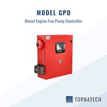
TORNATECH DIESEL ENGINE FIRE PUMP CONTROLLERS – MODEL GPD – INSTALLATION AND MAINTENANCE MANUAL
August 28, 2025
NAFFCO vs SIBCA – Which Fire Fighting Equipment Brand Are BETTER Choice in PAKISTAN?
August 28, 2025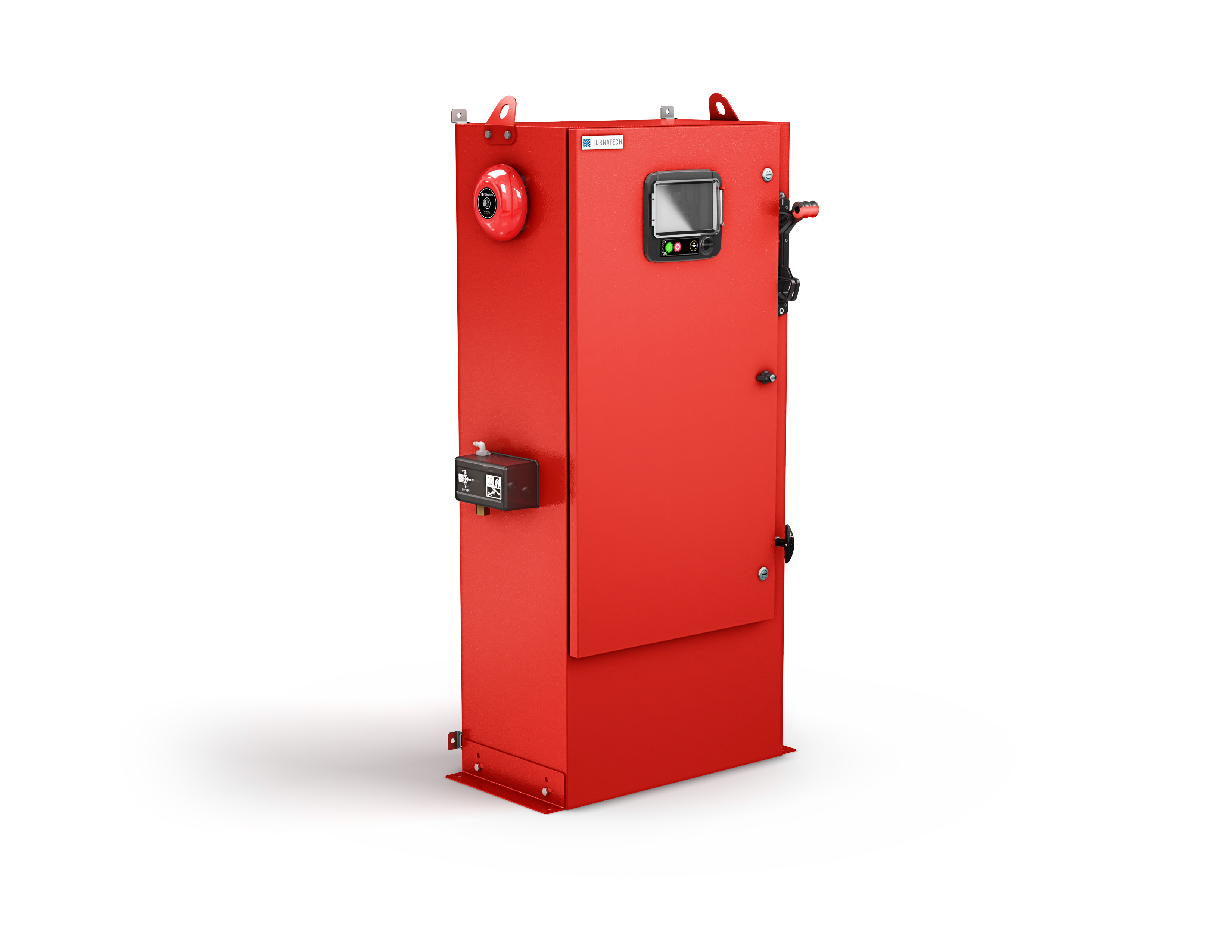
⚠️ Important Notice
- This manual must be read and understood before installing, operating, or servicing the controller.
- Installation and service should only be performed by qualified personnel familiar with fire pump controllers and NFPA standards.
Table of Contents
- Introduction
- General Description
- Installation
- Location
- Mounting
- Electrical Connections
- Water Connections
- Incoming Power
- Circuit Protection
- Terminal Descriptions
- Quick Start Guide
- Operation
- Front Panel (ViZiTouch)
- Alarms and Indicators
- Controller Functions
- Configuration
- Keypad & Security
- Date and Time
- Advanced Settings
- Inputs/Outputs
- Networking
- Reboot Functions
- History and Data Logging
- Events Log
- Pressure Curves
- Power Curves
- Statistics
- Downloads
- Service and Maintenance
- Routine Inspections
- Battery Maintenance
- Sensor Verification
- Firmware Updates
- Manuals and Technical Documents
- Standards Compliance (NFPA, UL, FM, CE)
- Certificates
- Wiring Diagrams
- Torque Values
1. INTRODUCTION
Diesel engine fire pump controllers are designed to automatically start and control diesel engines driving fire pumps when required by a fire protection system.
- Built in compliance with NFPA 20 standards.
- UL listed and FM approved.
- Provides both automatic and manual operation.
- Integrated dual battery chargers for reliable starting power.
- Equipped with ViZiTouch color touch screen HMI for monitoring and control.
The controller ensures reliable performance in emergency conditions, maintaining system pressure and complying with fire safety codes.
2. GENERAL DESCRIPTION
2.1 Overview
- Microprocessor-based diesel engine fire pump controller.
- Provides automatic starting from pressure drop or remote signals.
- Manual starting via local pushbuttons.
- Automatic shutdown option after 30 minutes of stable conditions.
2.2 Certifications
- UL Listed (Underwriters Laboratories)
- FM Approved (Factory Mutual)
- Complies with NFPA 20 (2013 Edition)
- Seismic certification in accordance with ICC-ES AC156, IBC, CBC
- EMC compliance with FCC and Industry Canada
2.3 Main Components
- Controller enclosure (floor-mounted or wall-mounted).
- Dual 12V or 24V battery charger system.
- Pressure transducer inputs.
- ViZiTouch 7” color touchscreen.
- Alarm and status relays.
- Event/data logging system.
3. INSTALLATION
The fire pump controller must be installed according to NFPA 20, local codes, and the manufacturer’s instructions. Improper installation may cause malfunction or damage.
3.1 Location
- Install in a clean, dry, well-ventilated area.
- Ambient temperature: 0 °C to +40 °C (32 °F to 104 °F).
- Humidity: max 90% non-condensing.
- Avoid exposure to vibration, corrosive gases, dust, or dripping water.
- Provide adequate clearance for door opening and maintenance access.
- Do not obstruct ventilation openings.
3.2 Mounting
- Controller may be wall-mounted or floor-mounted.
- Ensure solid support and vibration-free installation.
- Maintain accessibility to wiring terminals and fuses.
- Secure with appropriate anchors and hardware.
- Verify alignment and grounding.
3.3 Electrical Connections
⚠️ Safety Notes
- Only qualified electricians should perform connections.
- Disconnect all power sources before wiring.
- Follow local codes and NEC requirements.
Power Supply
- A dedicated circuit must supply AC power to the controller.
- Protection must be provided by a fuse or circuit breaker sized per rating label.
- Always connect both batteries before connecting AC power.
- Always disconnect AC power before disconnecting batteries.
⚠️ Disconnecting batteries while AC is connected may cause severe damage to electronics.
3.4 Water Connections
- Connect the system pressure sensing line to the pressure transducer input.
- Ensure all fittings are tight and leak-free.
- Provide a drain line for test operation.
3.5 Incoming Power
- Power supply requirements depend on model (see label inside door).
- Connect AC line and ground according to diagram.
- Verify correct voltage and frequency.
3.6 Circuit Protection
- Circuit breakers inside the controller provide protection:
- CB1 – Battery Charger 1
- CB2 – Battery Charger 2
- CB3 – Control circuit from Battery 1
- CB4 – Control circuit from Battery 2
Connection/Disconnection procedure:
- Connect both batteries → then AC power.
- Disconnect AC power → then batteries.
3.7 Terminal Descriptions
Alarm Output Terminals (DPDT Relays):
- Controller Trouble
- Engine Run
- Main Switch in Manual
- Main Switch in OFF
- Engine Trouble
- Pump Room Alarm
Field Inputs (Dry Contacts Only):
- Low Fuel Level
- Remote Automatic Start
- Deluge Valve Start
- Fuel Tank Leak
- High Fuel Level
- Engine RPM pickup
- ECM switch signals
- Suction Pressure
- Raw Water Temperature
- Raw Water Flow
- Low Engine Temperature
Engine Terminals:
- Fuel Solenoid Valve
- Engine Run
- Overspeed
- Oil Pressure
- Coolant Thermostat
- Battery 1 Positive
- Battery 2 Positive
- Start Contactor 1
- Start Contactor 2
- Ground
- Stop Fuel Solenoid Valve
Additional Terminals:
- Bell Output
- Test Solenoid Valve
- Analog Inputs (Pressure, Fuel Level, Flow, Temp)
- AC Monitoring
- CANBUS
- Factory reserved
3.8 Quick Start Guide
- Check rating label – verify correct model.
- Mount securely – wall or floor.
- Main Selector Switch OFF before wiring.
- Connect water lines to pressure sensor and drain.
- Wire engine terminals per diagram.
- Tighten connections to specified torque.
- Connect AC power + ground.
- Switch ON disconnects and breakers. Controller boots up.
- Complete First Setup on ViZiTouch screen (service code required).
- Verify sensors, voltage, and pressure calibration.
- Perform first engine start (selector to HAND).
- Check alarms, cut-in/cut-out pressure, weekly test settings.
- Set selector to AUTO – controller ready for service.
4. OPERATION
The controller is designed to operate the diesel engine-driven fire pump both automatically and manually, in compliance with NFPA 20.
4.1 Front Panel (ViZiTouch Interface)
The ViZiTouch is a 7-inch color touchscreen located on the front door of the controller, protected by a transparent cover.
Front Panel Components:
- A – Power LED (3 colors):
- Green (pulsing) → Normal power
- Yellow → Warning
- Red → Failure
- B – Temperature Sensor (for panel environment)
- C – Crank 1 Button: Start engine from Battery 1 (manual mode)
- D – Crank 2 Button: Start engine from Battery 2 (manual mode)
- E – Stop Button: Stops engine (when permitted)
- F – Run Test Button: Starts manual run test (water flows to drain)
- G – USB Port (front): For logs, updates, service reports
- H – Touchscreen Display: Main control interface
- I – Locking Mechanism: Push to unlock cover
- J – CANBUS Connector: Communication with IO board
- K – Side USB Port
- L – Ethernet Port
4.2 Alarms and Indicators
- Alarm Bell:
- Rings when a default NFPA alarm or configured condition occurs.
- Can be silenced (except critical alarms).
- If silenced, will sound again after 24h if condition persists.
- Automatically resets when alarm clears.
- Visual Indicators (on screen):
- Red = Alarm / Critical condition
- Yellow = Warning / Supervisory
- Green = Normal
- Audible Alarm:
- Built-in sounder or external bell output.
4.3 Home Screen
Displays the following real-time data:
- Battery voltages and charging currents
- AC status
- Starter sequence and timers
- Engine run/stop state
- Fuel solenoid valve status
- Engine alarms (oil pressure, temperature, overspeed, fail-to-start)
- System pressure (with cut-in/cut-out indicators)
- Controller mode (Hand / Off / Auto)
- Actuation mode (Pressure or Non-Pressure actuated)
- Shutdown mode (Manual or Automatic)
4.4 Controller Functions
Automatic Operation
- In AUTO mode, controller monitors discharge pressure.
- On pressure drop below cut-in setpoint:
- Starts engine via crank cycle sequence.
- Runs pump until pressure restored above cut-out.
- After a 30-min delay (if auto shutdown enabled), stops engine.
Manual Operation
- In HAND mode, operator can crank engine via Crank 1 or Crank 2 buttons.
- Engine runs until manually stopped.
Weekly Test
- Automatic weekly run test can be scheduled.
- During test, water flows through test drain line.
Remote Start/Stop
- Remote inputs allow external devices (deluge valve, supervisory panel) to start or stop the controller.
Engine Protection
- Overspeed, Fail-to-Start, and Engine Trouble alarms ensure safe operation.
- Oil pressure and coolant temperature monitored continuously.
- In AUTO mode → alarms only.
- In HAND/TEST mode → alarms may cause shutdown.
5. CONFIGURATION
The Configuration Menu is accessible from the ViZiTouch screen. It allows installers and authorized service personnel to set controller parameters. Access requires a user login code.
5.1 Keypad & Security
- Numeric keypad displayed on screen for entering passwords and settings.
- Multi-level security:
- User → limited access (basic settings)
- Technician → extended access (calibration, I/O setup)
- Factory/Service → full access (firmware, OEM settings)
5.2 Date and Time
- Adjust the internal real-time clock.
- Format: DD/MM/YYYY, HH:MM:SS
- Time zone selection available.
- Accurate time is required for logs and NFPA reporting.
5.3 Advanced Settings
- Modify system behavior (service level access only).
- Configure:
- Input/Output mapping
- Custom alarms and delays
- Engine control logic
- Crank/rest cycle timing
- Auto shutdown enabling/disabling
⚠️ Improper adjustment may void UL/FM approvals.
5.4 Inputs/Outputs
- Assign relays to alarms or supervisory signals.
- Configure contact logic (NO/NC).
- Assign analog inputs to:
- Pressure transducer
- Suction pressure sensor
- Fuel level sensor
- Flowmeter
- Raw water temperature sensor
5.5 Control Timers
Timers configurable in the menu:
- Crank Timer → duration of each crank attempt
- Rest Timer → delay between crank attempts
- Sequential Start Timer → delay for multiple pump systems
- Weekly Test Timer → scheduled automatic start time
- Auto Shutdown Timer → 30 min (adjustable)
- AC Fail Timer → delay before engine start on AC failure
5.6 Networking
- Ethernet port provides local or remote connectivity.
- Settings include:
- IP Address
- Subnet Mask
- Gateway
- Supports log download, remote monitoring, integration with building management systems.
5.7 Update Program
- Firmware/software can be updated using USB port.
- Insert USB stick → select update file → confirm.
- Controller reboots automatically after update.
5.8 Reboot Functions
- Reboot ViZiTouch only (touch panel restart).
- Full Controller Restart (all circuits reset).
- Used after updates or configuration changes.
6. HISTORY AND DATA LOGGING
The controller continuously records events, alarms, and performance data. This log is non-erasable and complies with NFPA 20 requirements.
6.1 Events Log
- Stores a chronological list of all system events.
- Typical entries include:
- Automatic start signals
- Manual starts/stops
- Alarm activations
- Battery/charger failures
- Pressure changes
- Weekly test activations
- Each entry includes:
- Date
- Time
- Event description
- User (if logged in)
⚠️ Events cannot be deleted or modified.
6.2 Pressure Curves
- Graphical record of system discharge pressure.
- Useful for analyzing pump performance during tests or real fire events.
- Provides zoom and scrolling for detailed review.
- Helps verify pump meets rated performance curve.
6.3 Power Curves
- Tracks battery voltage and charging current over time.
- Used to diagnose charger or battery health issues.
- Identifies weak batteries or charger malfunctions.
6.4 Statistics
Three categories of cumulative statistics:
- All Time Statistics:
- Total engine hours
- Number of starts (auto/manual/remote)
- Alarm counts
- Weekly test runs
- First Service Statistics:
- Data recorded from commissioning until first scheduled maintenance.
- Provides a baseline for system performance.
- Last Service Statistics:
- Data from last service to present date.
- Used for maintenance verification and trend analysis.
6.5 Saved Logs
- Specific periods can be saved for later review.
- Logs can be tagged and stored in controller memory or exported.
6.6 Downloads
- Data can be downloaded via:
- Front USB port
- Ethernet port
- File formats: CSV / TXT / proprietary logs.
- Data can be used for:
- NFPA inspection reports
- Maintenance documentation
- Troubleshooting analysis
7. SERVICE AND MAINTENANCE
The fire pump controller requires regular inspection and maintenance to ensure reliable operation during emergencies. All procedures must follow NFPA 20, local codes, and manufacturer guidelines.
7.1 Routine Inspections
- Inspect controller enclosure for:
- Cleanliness, no dust or moisture
- Secure mounting, no vibration damage
- Door and lock functionality
- Check indicator LEDs and touchscreen for proper display.
- Verify alarm bell and audible signals.
- Review event log for abnormal entries.
- Confirm controller mode switch is in AUTO position.
7.2 Battery Maintenance
- Verify both batteries are connected and secure.
- Measure voltage levels:
- 12V system → >12.5V
- 24V system → >25V
- Inspect terminals for corrosion and tighten connections.
- Verify charging current from both chargers.
- Replace batteries at intervals recommended by NFPA 25 or manufacturer.
7.3 Sensor Verification
- Pressure transducer: Verify calibration and cut-in/cut-out points.
- Fuel level sensor: Test alarm for low and high level.
- Flow and temperature sensors: Verify readings during test runs.
- Suction pressure sensor: Confirm accuracy if installed.
7.4 Firmware Updates
- Insert USB flash drive with latest software version.
- Navigate to Update Program in configuration menu.
- Confirm update → system reboots automatically.
- Verify successful update in system information menu.
7.5 Preventive Maintenance
- Perform weekly test run to verify operation.
- Inspect wiring for loose or damaged connections.
- Test remote start inputs (deluge valve, remote pushbutton).
- Test all alarms (oil pressure, overspeed, fail to start, charger failure).
- Confirm correct operation of Auto Shutdown feature if enabled.
7.6 Service Records
- Record all inspections, test results, and service actions.
- Keep service logbook in pump room per NFPA 25.
- Download logs periodically for compliance audits.
8. MANUALS
The controller includes access to digital manuals and documentation directly through the ViZiTouch interface.
- Manuals can be viewed on screen or downloaded via USB/Ethernet.
- Included content:
- Installation instructions
- Operation guide
- Maintenance schedules
- Troubleshooting procedures
- NFPA references
This feature ensures operators always have the correct technical references at hand.
9. TECHNICAL DOCUMENTS
The controller complies with multiple international standards and certifications.
9.1 Standards Compliance
- NFPA 20 (2013 Edition) – Installation of Stationary Fire Pumps
- NFPA 70 (NEC) – Electrical installation compliance (USA)
- Canadian Electrical Code – CEC compliance (Canada)
9.2 Certifications
- UL Listed (Underwriters Laboratories)
- FM Approved (Factory Mutual)
- Seismic Certification – ICC-ES AC156, IBC 2015, CBC 2016
- FCC / Industry Canada RSS – EMC compliance
9.3 Technical References
- Manufacturer’s wiring diagrams (supplied with each unit)
- Dimension drawings for enclosure sizes
- Torque specifications for all connections and terminals
- Factory service bulletins and updates
Download Complete O&M of Tornatech Electric Fire Pump Model GPY
#TornatechFirePumpController #TornatechControllerPakistan #ElectricFirePumpControllerPakistan #VizitouchControllerPakistan #TornatechVizitouch #FirePumpControllerPakistan #TornatechControllersLahore #TornatechControllersKarachi #TornatechControllersIslamabad #TornatechRepairPakistan #TornatechMaintenancePakistan #TornatechSparesPakistan #ElectricFirePumpControllersPakistan #AutomaticFirePumpControllerPakistan #ManualFirePumpControllerPakistan #TornatechControllerServicePakistan #VizitouchFirePumpController #VizitouchPakistan #TornatechVizitouchPakistan #TornatechAuthorizedDealerPakistan #TornatechControllerPartsPakistan #FirePumpControllersPakistan #ULFMCertifiedFirePumpControllerPakistan #NFPA20FirePumpControllerPakistan #BestFirePumpControllersPakistan #TopFirePumpControllerPakistan #TornatechControllerTechniciansPakistan #FirePumpControllerServicePakistan #FirePumpControllerMaintenancePakistan #TornatechControllerInstallationPakistan #TornatechControllerTestingPakistan #TornatechControllerSupportPakistan #TornatechControllerSupplierPakistan #FirePumpControllerSparePartsPakistan #ElectricPumpControllerPakistan #TornatechFirePumpSpareParts #VizitouchScreenControllerPakistan #TornatechPanelPakistan #FirePumpPanelPakistan #FirePumpPanelControllerPakistan #TornatechControllerCalibrationPakistan #TornatechControllerInspectionPakistan #FirePumpControllerExpertsPakistan #FirePumpControllerCompanyPakistan #BestTornatechControllerPakistan #TornatechVizitouchRepairPakistan #VizitouchServicePakistan #VizitouchMaintenancePakistan #TornatechVizitouchLahore #TornatechVizitouchKarachi #TornatechVizitouchIslamabad #ElectricEngineFirePumpControllerPakistan #TornatechElectricControllerPakistan #TornatechAuthorizedServicePakistan #TornatechCertifiedTechniciansPakistan #TornatechControllerTroubleshootingPakistan #FirePumpControllerULFMPakistan #NFPAControllerPakistan #FirePumpSystemControllerPakistan #TornatechControllerSolutionsPakistan #TornatechControllerUpgradesPakistan #TornatechControllerPakistanMarket #VizitouchTouchScreenPakistan #VizitouchControllerSupportPakistan #FirePumpControllerSpecialistsPakistan #TornatechControllerDealersPakistan #TornatechControllerDistributorsPakistan #TornatechControllersServiceCenterPakistan #TornatechControllerOEMPakistan #TornatechControllerAnnualMaintenancePakistan #TornatechControllerEmergencyRepairPakistan #FirePumpControllersLahore #FirePumpControllersKarachi #FirePumpControllersIslamabad #FirePumpControllersPakistanSuppliers #TornatechPakistan #TornatechMiddleEastPakistan #TornatechVizitouchSupportPakistan #FireSafetyControllersPakistan #TornatechEngineControllerPakistan #FirePumpControllerContractorsPakistan #TornatechControllersNFPA20Pakistan #ElectricFirePumpSystemsPakistan #TornatechControllersExpertsPakistan #VizitouchPanelPakistan #VizitouchULFMPakistan #VizitouchNFPA20Pakistan #TornatechControllersPakistanMarket #TornatechControllersNearMePakistan #TornatechControllersPakistanDealers #FirePumpControllerRepairPakistan #TornatechControllerUpkeepPakistan #FirePumpSystemPakistan #TornatechControllerPakistaniTechnicians #TornatechControllerPakistaniSuppliers #TornatechControllerPakistaniMarket #FirePumpControllerPakistaniService #TornatechSparePartsPakistan #ElectricFirePumpControllerSparesPakistan
